Controls 1
Controls 1
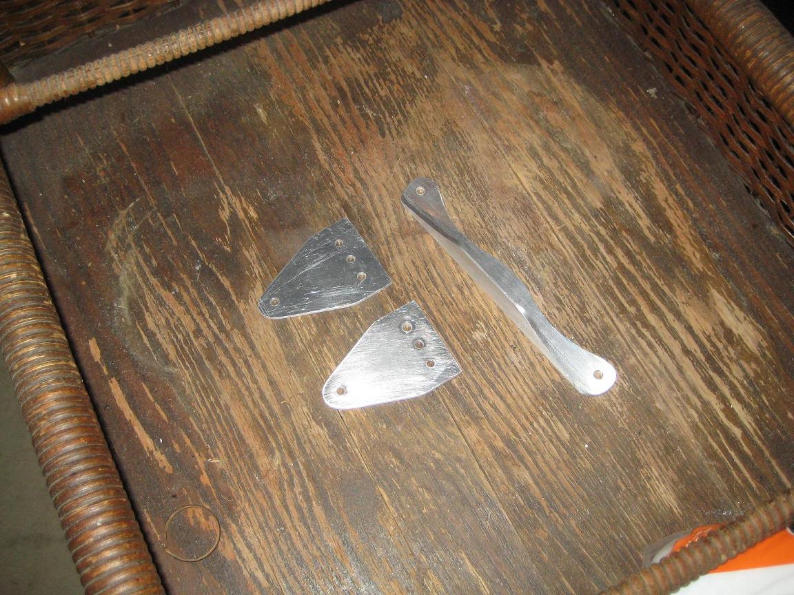
I've started making aluminum components for my control system out of 6061-T6 aluminum. Pictured below are two arms of the aileron bellcrank assembly (I started with the easiest pieces), and also my elevator control arm.
I'm spray-gluing CAD paper templates of the components onto the metal pieces, then rough-cutting them out with any tool that seems to work (hacksaw, dremel, grinding wheel). Final shaping is achieved with an arsenal of files. All metal components must be deburred, to remove any filings and rough edges which might encourage cracking.
Aluminum components will be sanded clean, treated with Alumiprep, alodyned, and painted with epoxy primer.
I'm saving a lot of my metal work for this winter (2013) when the temperatures get too low for using epoxy.
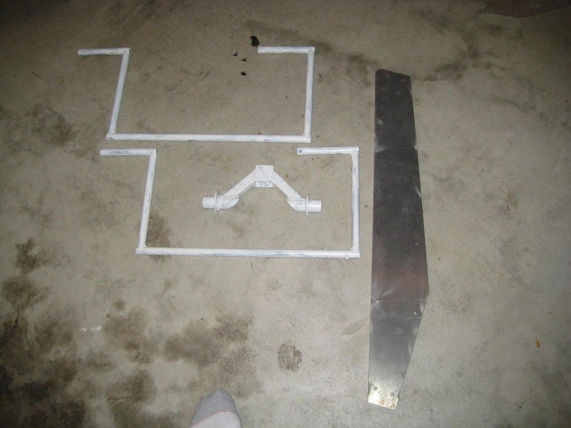
To the left (painted white) are my rudder pedals and my control column assembly. A friend put some nice fish-mouth joints on the rudder pedals. A local machine-shop welded all of this together. The control column assembly is basically a single-stick version of Mark Langford's double-stick setup.
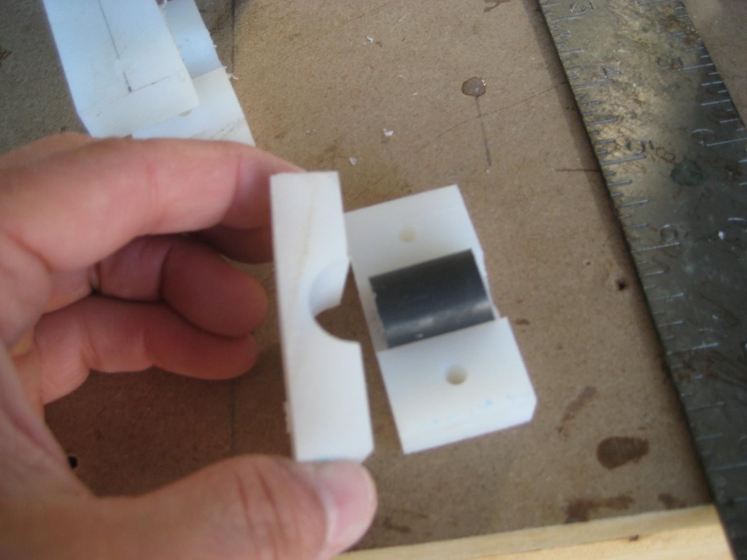
Above: I'm using nylon blocks to mount my rudder pedals. Spare pieces of 4130 steel tubing helped keep things in place while I used the drill press.
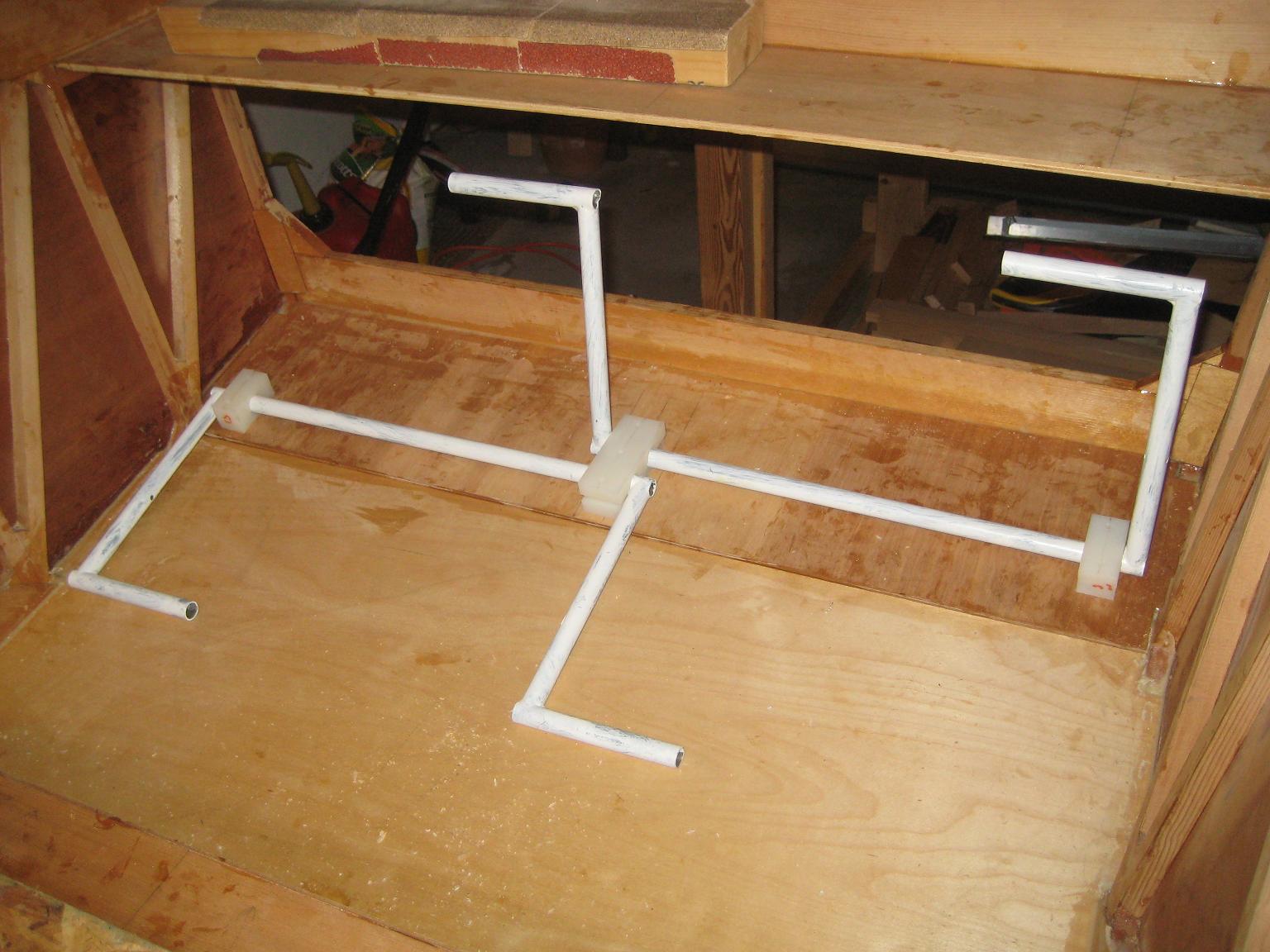
Mounting holes for the rudder pedals have now been drilled through the bottom of the boat. The 5048-45 spars are taller than stock, and this does become a minor factor in rudder pedal placement. Your knees are going to be a little higher in the cockpit, making your calves a little "shorter." Mine are pretty short to begin with.
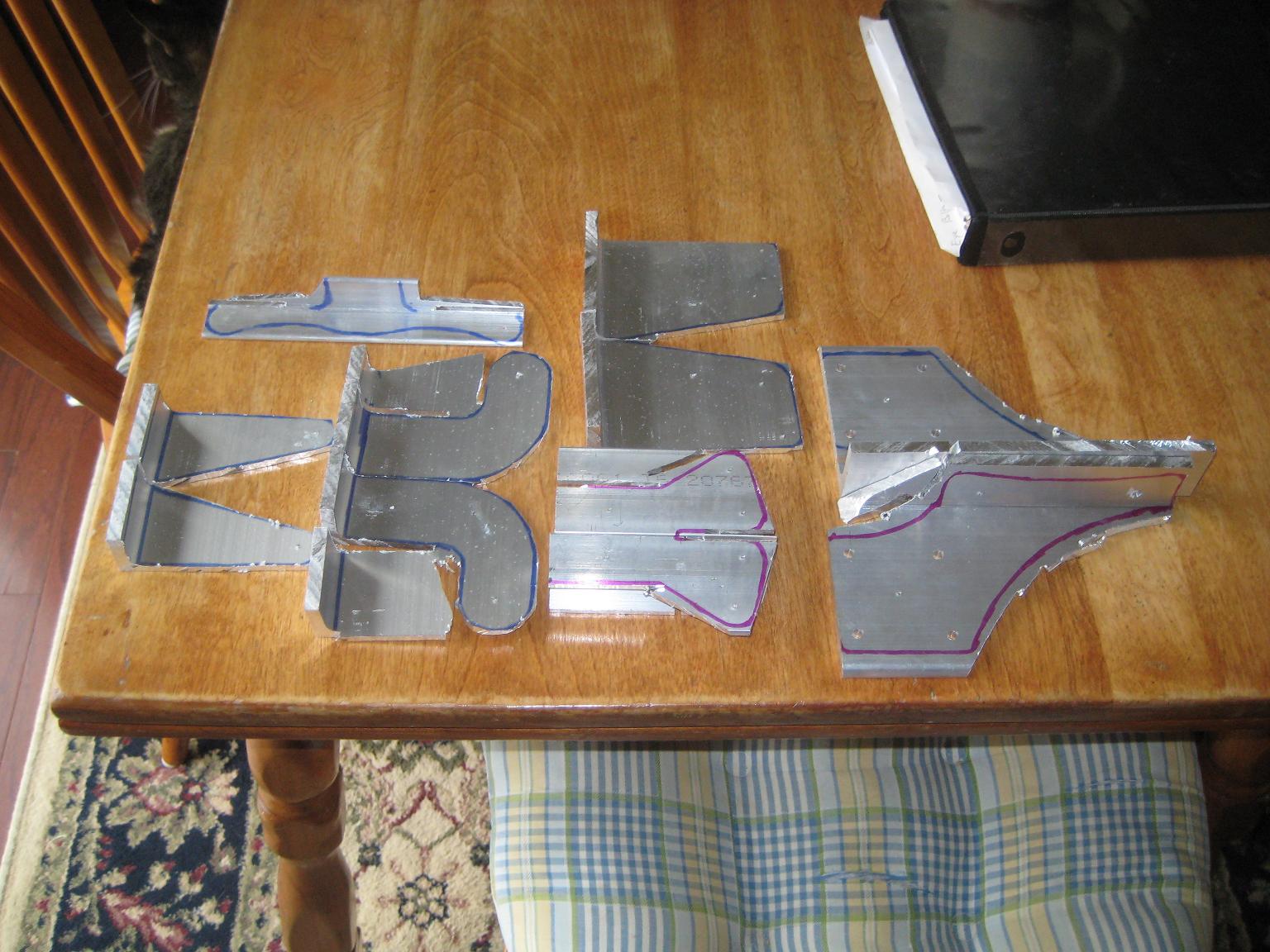
Many rough hunks of unshaped aluminum control components will keep me busy cutting, filing and sanding through Thanksgiving 2013, at least. There are more of them than are pictured here.
I found it better to tape my paper templates to the metal control components, and then trace around them with permanent marker before cutting, than it was to keep the paper spray-glued to the metal while cutting. The various bolt-holes have all been marked with a punch before drilling and shaping. It is definitely best to drill all your holes perfectly and test-fit them before shaping the outside edges of the pieces.
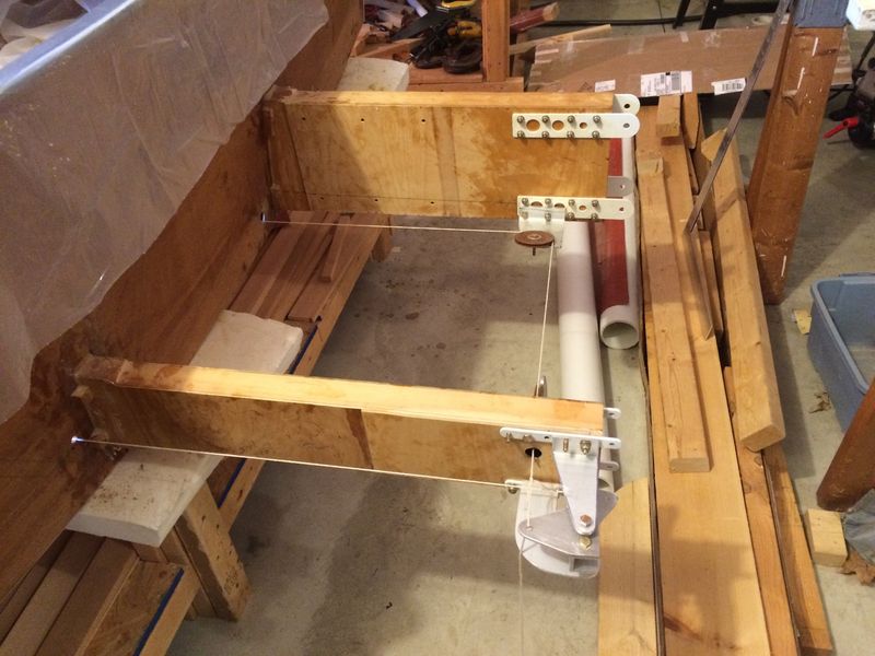
Here I'm using string as "control cable" as I drill the mounting holes for all the components in my aileron control system. The string helped me align everything. The system is based closely on the plans. However, the 5048 spars I'm using are taller than plans, and the airfoil has a significantly different profile. This led me to 1) invert the bottom mounting brackets on the back of the rear spars and 2) add guide pulleys to the front of the rear spars. See below regarding the extra pulleys.
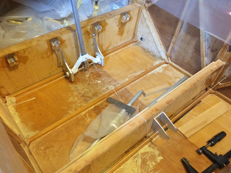
Here you see the "control cable" string attached to the control stick assembly in front, and passing through holes drilled in the elevator horn mounting bracket in back. It was very cool to be able to move the control stick and see the aileron bell cranks do their thing! As you can see, my garage shop is an absolute mess at this point. But things are definitely moving forward now.