Wings 2
Wings page 2
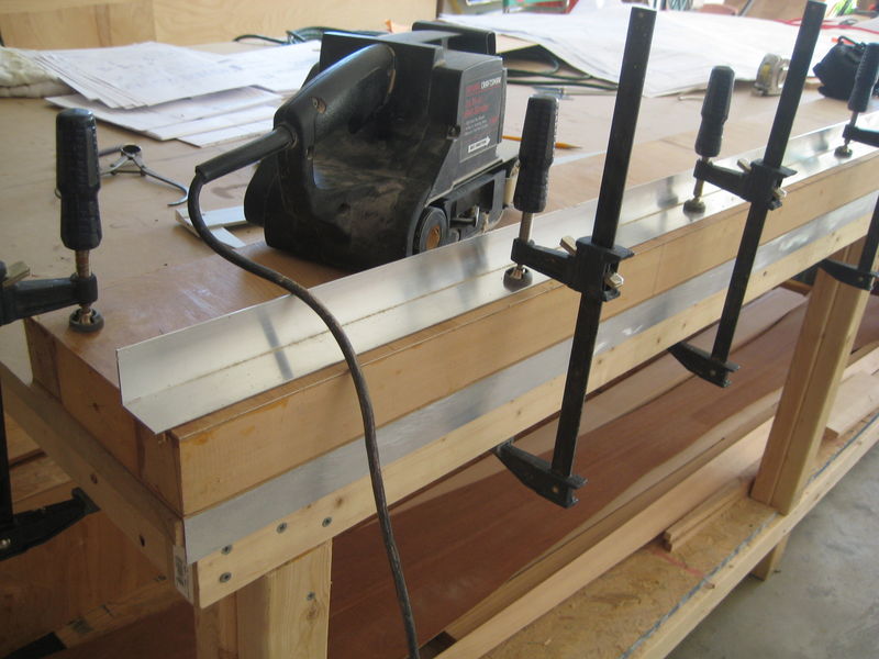
Below is how I sanded the angles of the wing profiles into my spars. The spars were first marked (just at their roots and tips) according to measurements taken from the airfoil templates. Then I sandwiched each spar between two long, cheap pieces of aluminum angle. Notice how the bottom piece of angle serves as the edge of my worktable. Position the angle and spar as necessary, clamp the angle down on the spar firmly, and go at the exposed wood with a belt sander. The metal will protect the wood and allow you to get nice, clean, straight and remarkably accurate airfoil angles in your spars.
The wings of the KR are designed to be removeable. Here you see the wing attach fittings (WAFs) which connect the center spars to the outer spars of the airplane. They're made of 1/8" thick 4130 steel--very tough stuff. I copied the plans drawings to CAD with a primitive free program called Tiger Cad, which worked beautifully for me. I gave the CAD drawing to my local machine shop and they cut the WAFs out with a laser. As with all my steel components, I sandblasted them (thanks to the generosity of my EAA technical counsellor who let me use his equipment), etched them with liquid etcher, and painted them with epoxy primer. I'll put a more attractive top-coat of paint on them later.
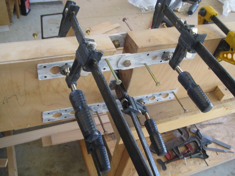
I agonized a lot about the 64 holes I had to drill through my expensive spars for the WAFs. One mistake would mean at least $200 and 100 hours of work down the pot. However, using a home-made drilling guide, I was able to drill all the holes perfectly. As you can see, I used all sorts of vices and bolts to keep the WAFs from slipping as I drilled. Notice also how I separated my work tables to create a gap, so that I could maneuver my 12" drill around for the bottom WAFs. The tables have to be perfectly level with each other, of course.
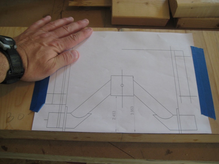
NOTE: Before cutting the WAFs for your REAR spars, I suggest looking very carefully at the plans. In the KR builder's manual, the rear WAFs as presented are designed for the KR-2, not the KR-2S. Whereas the KR-2 wing trailing edges sweep forward at a 2 or 3 degree angle, the 2S wing trailing edges sweep forward at a 6 degree angle. I'm pretty sure this will make a difference in how your rear WAF bolt holes line up. I drew my rear spar junctions exactly as they would come together in real life and modified my rear WAFs accordingly so all the bolt holes would line up correctly. If I remember right, in fact, I also made the outer rear spar WAFs slightly longer than represented in the plans to compensate for the difference in sweep angle.
While drilling the WAF holes, the back sides of your front spars must be perfectly aligned with each other. A laser cast across both my perfectly level worktables provided the baseline.
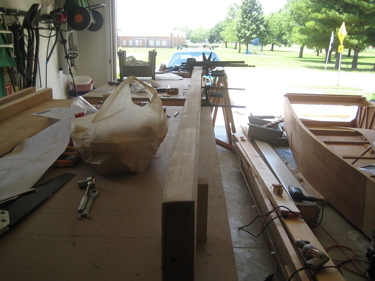
This is a wider view of the same operation. While drilling your WAF holes, you are setting the dihedral of your wings (dihedral is the tilt from root to tip). In the plans, the outer wings have a one foot fiberglass extension on the end of the wings. I've eliminated the extension and continued the wooden spar structure to the tip. As far as the dihedral was concerned, I was pleased to find that my wing tips on both sides were within 1/64" of each other, measured up from the table surface, even after having sanded the airfoil profiles into the spars.
Using a drill press, I drilled mounting holes for my control column assembly and landing gear brackets through the forward center spar before inserting the spar into the fuselage. Here I'm using a template of my control column assembly to determine exactly where the mounting holes should be. For the control column assembly, I had the foresight to epoxy extra spruce mounting blocks into the spar before covering it with plywood. This is not really necessary, but if I can avoid drilling holes through my spar caps, I'll do it.
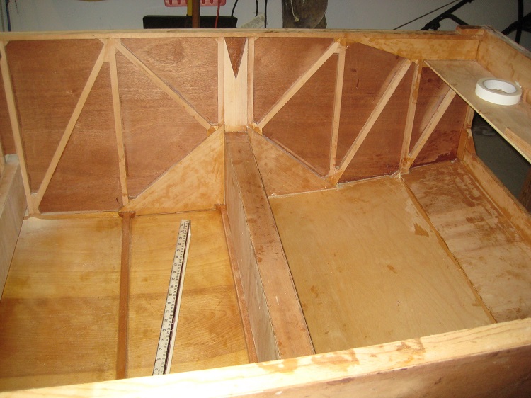
The forward center spar has been epoxied into the boat. One side sticks out of the boat about 1/32" more than the other. My darned airplane will always be flying in right-hand circles.

I've cut out the AS5048-45 airfoil profiles roughly with a scroll saw and placed them over the spars. The forward spar is epoxied into the boat, but the rear spar is floating free at this point in its slot. This is how you set the angle of incidence of your wings (the angle of the wing when viewed in profile). Move the rear spar up and down until everything is perfectly level and the correct angle of incidence is established, then lock everything in with wooden blocks and epoxy.
Now that my rear center spar is epoxied in, I can make a few decisions about seating, rudder pedal placement, brake configuration, and canopy height.